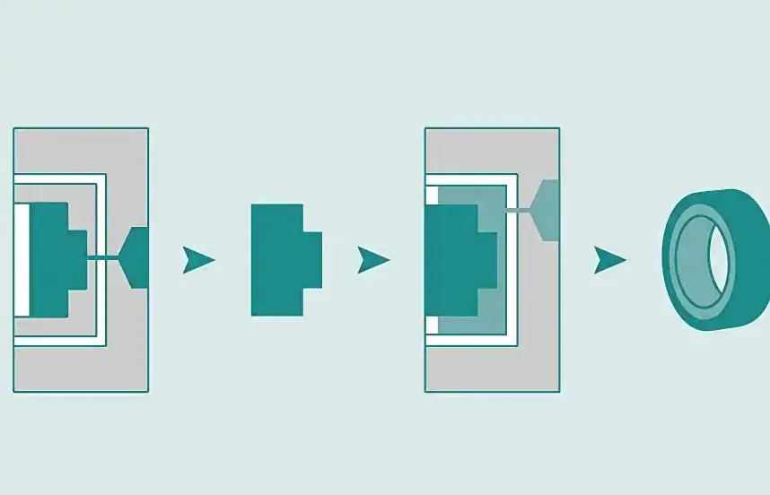
Overmolding enables manufacturers to combine multiple materials into a single, functional component—improving grip, sealing, durability, and aesthetics. However, even the best material selection and molding equipment cannot compensate for poor part design.
In overmolding, design mistakes are magnified. Improper wall thickness, sharp corners, or insufficient draft can lead to warpage, delamination, sink marks, poor bonding, and costly tooling rework.
This article provides a detailed design guide to overmolding part design, focusing on the three most critical geometric factors:
- Wall thickness
- Radii and corner transitions
- Draft angles
Understanding and applying these principles early in the design stage will significantly improve part quality, reduce cost, and shorten time to production.
Why Overmolding Design Is More Complex Than Standard Injection Molding
Overmolding introduces challenges not present in single-material molding, including:
- Two materials with different shrink rates
- Different cooling behaviors
- Bonding interface sensitivity
- Higher cosmetic and functional requirements
Because of this, traditional injection molding design rules must be adapted for overmolding applications.
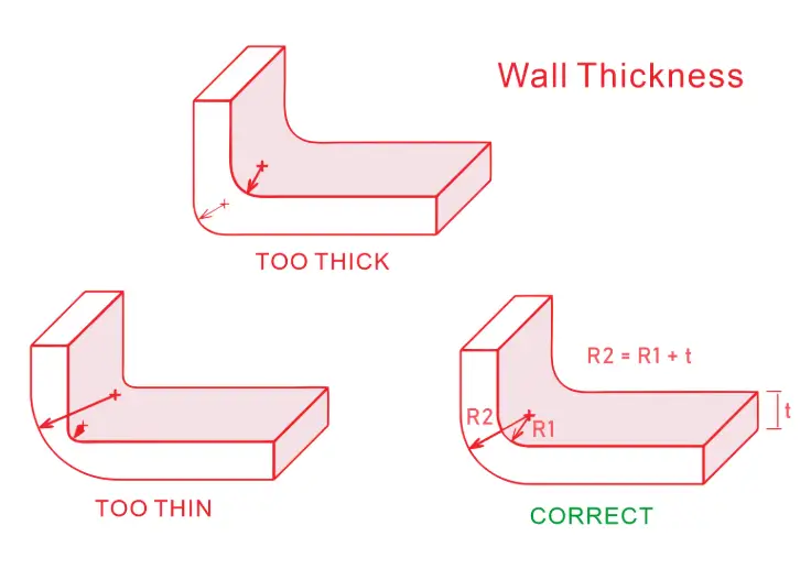
Wall Thickness in Overmolding Part Design
Why Wall Thickness Matters
Wall thickness directly affects:
- Material flow
- Cooling time
- Bonding strength
- Part warpage
- Cycle time and cost
In overmolding, both the substrate wall thickness and the overmold thickness must be optimized together.
Recommended Wall Thickness for Substrate Parts
For the rigid substrate (first shot), recommended wall thickness typically ranges from:
- 1.5 – 3.0 mm for most engineering plastics
- 2.0 – 3.5 mm for fiber-reinforced materials
Key design rules:
- Maintain uniform wall thickness
- Avoid sudden thickness changes
- Gradually transition between thick and thin sections
Uneven substrate thickness often leads to:
- Sink marks
- Internal stress
- Poor overmold adhesion
Recommended Wall Thickness for Overmold Layers
Overmold materials such as TPE, TPU, or silicone generally require:
- 0.6 – 1.5 mm for functional overmolds
- 1.0 – 2.5 mm for grip or cushioning features
Overmold layers that are too thin may:
- Fail to bond properly
- Tear during use
- Show flow hesitation marks
Overmold layers that are too thick increase:
- Cycle time
- Material cost
- Risk of deformation
Wall Thickness Ratios Between Substrate and Overmold
A commonly used design guideline:
- Overmold thickness = 30% – 60% of substrate thickness
Balanced thickness improves:
- Thermal compatibility
- Adhesion strength
- Dimensional stability
Avoiding Thick-to-Thin Transitions
Sudden transitions cause:
- Flow imbalance
- Trapped air
- Bonding defects
Design solutions include:
- Gradual tapers
- Stepped thickness with radii
- Strategic material flow direction
Radii and Corner Design in Overmolding
Why Radii Are Critical in Overmolding
Sharp corners are one of the most common causes of overmolding defects.
Problems caused by sharp edges:
- Stress concentration
- Incomplete overmold fill
- Poor material flow
- Delamination at corners
Radii improve both moldability and long-term durability.
Recommended Internal and External Radii
General guidelines:
- Internal radius ≥ 0.5 × wall thickness
- External radius = internal radius + wall thickness
For overmolded parts, increasing these values improves:
- Material flow
- Bonding strength
- Cosmetic appearance
Radii at the Overmold Interface
The interface between substrate and overmold is the most critical zone.
Best practices:
- Avoid sharp steps at bonding interfaces
- Use rounded transitions to allow smooth material flow
- Incorporate mechanical locking features with radiused edges
Radii improve mechanical interlock performance and reduce peel forces.
Fillets vs Chamfers
In overmolding:
- Fillets are preferred over chamfers
- Chamfers often create flow hesitation and thin edges
- Fillets provide smoother transitions and better bonding
Draft Angles in Overmolding Design
Why Draft Is Essential
Draft angles allow parts to be ejected from the mold without damage.
In overmolding, draft is required for:
- Substrate mold
- Overmold tool
- Any shut-off surfaces
Insufficient draft can cause:
- Part sticking
- Tearing of soft overmold
- Tool wear and damage
Recommended Draft Angles for Substrate Parts
Typical guidelines:
- 1° – 2° per side for textured surfaces
- 0.5° – 1° per side for polished surfaces
When the substrate will be overmolded, additional draft helps ensure:
- Accurate part placement
- Reliable shut-off sealing

Draft Requirements for Overmolded Materials
Soft materials require more draft due to flexibility and friction.
Recommended draft angles:
- TPE / TPU: 2° – 5° per side
- Silicone (LSR): 3° – 7° per side
Higher draft angles reduce:
- Tearing risk
- Ejection force
- Cosmetic defects
Draft on Shut-Off and Bonding Areas
Shut-off surfaces must:
- Seal precisely
- Release cleanly
Best practices:
- Use minimal but sufficient draft
- Avoid zero-draft conditions
- Polish shut-off surfaces where possible
Designing for Bonding Strength
Mechanical Bonding Features
Overmolding relies on:
- Chemical adhesion
- Mechanical interlocking
Design features that improve bonding include:
- Undercuts
- Grooves
- Through-holes
- Textured surfaces
These features should be designed with:
- Adequate radii
- Proper draft
- Uniform wall thickness
Avoiding Bond Line Failures
Common causes of bond failure:
- Thin overmold edges
- Sharp corners
- Inconsistent wall thickness
Good geometry improves bonding as much as material choice.
Common Overmolding Design Mistakes
- Zero draft on soft materials
- Overmold too thin at edges
- Sharp internal corners
- Excessive wall thickness variation
- Ignoring shrinkage differences
Each of these increases cost and risk.
Tooling and Manufacturing Impact
Good design directly affects:
- Tool complexity
- Cycle time
- Scrap rate
- Tool life
Designing with proper wall thickness, radii, and draft:
- Simplifies tooling
- Improves yield
- Reduces rework
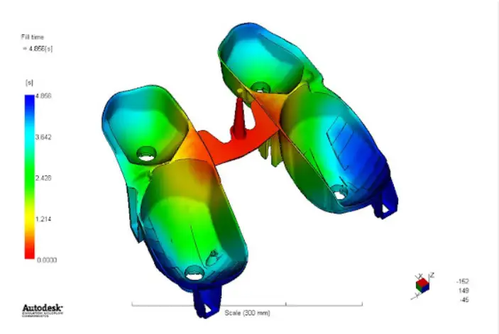
Simulation and DFM Validation
Modern overmolding projects increasingly rely on:
- Mold flow simulation
- DFM (Design for Manufacturability) reviews
- Prototype validation
Simulation helps predict:
- Flow hesitation
- Air traps
- Bonding quality
Industry-Specific Considerations
Medical Overmolding
- Smooth radii for cleanability
- Controlled wall thickness for consistency
- Generous draft to protect soft materials
Automotive Overmolding
- Robust radii for durability
- Thick-to-thin control for vibration resistance
- Draft optimized for high-volume automation
Consumer Electronics
- Thin, consistent overmolds
- Cosmetic-grade radii
- Precision draft control
Best Practices Checklist
- Maintain uniform wall thickness
- Use generous internal radii
- Avoid sharp edges
- Apply sufficient draft for soft materials
- Design bonding features with radii and draft
Early design review saves time and money.
Final Thoughts: Designing Better Overmolded Parts
Successful overmolding starts with geometry, not materials or machines.
By carefully designing wall thickness, radii, and draft, engineers can:
- Improve bonding strength
- Reduce manufacturing defects
- Extend product lifespan
- Lower total production cost
Overmolding rewards thoughtful design—and penalizes shortcuts.
If you are developing an overmolded component, engaging with an experienced overmolding manufacturer during the design phase is the most effective way to ensure success.